How Do You Make Architectural Hatches Clear and Accurate?
A clear hatch identifies a material or shows a real layout without hiding the drawing. These 13 visual checks explain how to size it, align it, show joints and print it accurately.
What does a hatch tell me?
It identifies a material, or shows the actual joints in a finish. Decide which before drawing it.


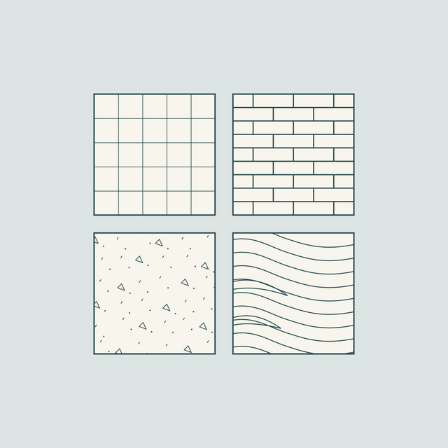
Samples from PDA’s Concrete, Timber and Insulation pattern libraries. These images identify finishes or materials; they do not set real joint dimensions. Label materials in the drawing legend.


REVIT
Should the hatch follow the view scale?
For actual tiles, yes. Smaller views must show the same real tile size.


In Revit, use Model for actual tile or brick layouts. Use Drafting for material symbols that should remain readable on the sheet.
Does tile spacing include grout?
Yes. One repeat includes one tile and one joint.


The 3 mm joint (≈ 0.12″) is enlarged here for clarity. Check the tile’s actual size: a nominal size may already include a joint allowance.

Line or visible gap?
Use one thin joint line in a small-scale plan. Show both tile edges in a large detail.


A 3 mm joint prints only 0.06 mm at 1:50 (≈ 0.0024″), but 0.60 mm at 1:5 (≈ 0.0236″). Figures are explanatory enlargements, not print-to-scale samples.
What happens at the wall?
Show the perimeter movement joint separately from ordinary tile joints.


Illustrative floor build-up, not a construction specification. Joint width, sealant, backing and any trim must follow the project specification. Do not add this perimeter allowance to every tile repeat.

AUTOCAD · DRAWING UNITS: MM
How do I get the right repeat?
Required repeat ÷ measured repeat at scale 1 = hatch scale.


600 ÷ 30 = 20. Set the hatch scale to 20, then measure again. This example uses millimetre drawing units; another pattern can need a different multiplier.
A 600 mm / ≈ 23.62″ repeat on paper
| View | Printed mm | Printed inches ≈ |
|---|---|---|
| 1:20 | 30 | 1.181″ |
| 1:50 | 12 | 0.472″ |
| 1:100 | 6 | 0.236″ |
How light should the hatch be?
Walls and labels should be easier to read than the hatch.


Only lineweight changes here. Keep real tile spacing fixed and print a small test at the final size.

AUTOCAD / REVIT
Why don’t the joints align?
Use the same origin, spacing and angle for one continuous finish.


Origin means the pattern’s starting point. AutoCAD: specify the same origin. Revit: align model-pattern lines to a common reference.

How do I avoid narrow edge cuts?
Try moving the whole grid by half a repeat. Do not stretch the tiles.


Shift: 250 mm / ≈ 9.84″ for a 500 mm / ≈ 19.69″ repeat. The centreline stays fixed. Width excludes perimeter allowances; joint details determine the final tile cuts.
AUTOCAD
How do I keep openings clear?
Include a closed boundary around each opening.


With Select Objects, select both the floor outline and the shaft outline. With Pick Points, check island detection: it recognises enclosed holes.
ILLUSTRATOR
How do I resize only the pattern?
Turn Transform Objects off and Transform Patterns on.


Object → Transform → Scale. The dashed outline is the original room. At 1:50, a 600 mm repeat is 12 mm on paper (≈ 0.47″). If the current repeat is 10 mm, use 120%.

PDF EXPORT
How do I keep exported lines sharp?
Export directly to PDF with vector lines preserved.


Both samples show the same crop at the same enlargement. Inspect the exported PDF: some effects and export settings convert paths into pixels.
PRINTING
How do I check the printed scale?
Print at 100%, then measure a 100 mm / ≈ 3.94″ check bar.


Use the intended paper size. A3 reduced to A4 is about 70.7%; 1:50 becomes approximately 1:70.7. For Letter or Tabloid, prepare that sheet size before export.

Five fixes in one floor plan
The room stays unchanged. Only the hatch is corrected.


- Repeat: bracket 1 measures one tile repeat: 500 mm / ≈ 19.69″ after correction.
- Alignment: marker 2 identifies where the two hatch areas meet. The joints must continue straight.
- Edge: bracket 3 measures the left edge band: 270 mm / ≈ 10.63″ after correction. The right band is equal.
- Opening: marker 4 points inside the shaft, which must stay clear.
- Lineweight: marker 5 touches a hatch line. It should be lighter than the wall outline.
Illustrative hatch exercise. Dimensions refer to the internal floor area; wall thickness is schematic. Width excludes perimeter allowances; final tile cuts depend on the joint detail.
Dimensions are metric with rounded inch equivalents marked ≈. Diagrams explain relationships and are not printable scale templates.
Product links contain Illustrator AI files, not AutoCAD or Revit PAT files. The paid 17-set pack contains the full collection; its free Wall Cross Section option is only that subset.
Keep real sizes accurate, align continuous joints and let walls and labels remain prominent. Check the exported PDF, then measure the final print before issuing the drawing.
0 Comments
There are no comments for this article. Be the first one to leave a message!